SO WHAT IS THE FINAL PRODUCT OF THE PROJECT SUPPOSE TO LOOK LIKE
FINAL TESTINGS
Test Report 1
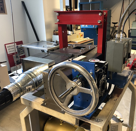
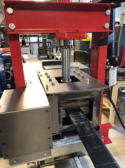
Introduction: The composite material (1/4”x 3”x 5’) of a Boeing 777x wing is going to be delaminated by a ram pressing two claw shaped devices together to bend the material. The bent material must stay in place without jamming, breaking and ejecting the material improperly. Once the material has gone through in and out properly in the delamination process in the frame body it will then go into the chipper process to be shredded.
Requirements: The 1/4” material after being delaminated it must not be more than 1” thick. The material must not get jammed. The material must move along the delamination process in less 30 seconds from entering and exiting the frame body of the mechanism.
Parameters of interest: The material will roughly be 1/2” thick after delamination process and will take around 30 seconds to complete from entrance to exit of frame body.
Predicted performance: The feed and delamination process will work together to have a good outcome.
Data acquisition: As the feed is running and delamination ramming down on the material it is important to listen to the sound inside the frame body. Bad noise will indicate something went wrong.
Schedule: Testing this plan will take an approximate 30 minutes.
Method/Approach: This testing is going to be elaborate and easy way to test this plan. The things needed is a timer, caliper, and the composite material. This is a three-person job. There will be one person holding the material to go in the entrance of the frame body, another turning the hand wheel to make the feed run, and the third person working the ram to do the delamination.
There will need to be data taken. There is will need to be a caliper to help measure how thick the board is in the beginning and at the end. A time recorded as to how long the process took, and while its running how was the sound of the feed: normal sound or bad sound. There will be 4 steps that will need to be repeated 3 times. Data will be taken in a table like the one listed below.
Test Report 2
Requirements
-
The 1/4” thick material must be able to go through the frame body in between the shafts with the spring rate constant increasing the griping force on the composite boards.
-
It must grip the material to increase the material going through to 1.5-2.5 inches.
-
The hand wheel must turn the feed rate at 20 revolutions per minute.
Parameters of interest: The material will roughly be 1/4” thick after delamination process and will take around 5 minutes to complete one trial run of testing.
Predicted performance: The feed and delamination process will work together to have a good outcome.
Data acquisition: As the feed is running and delamination ramming down on the material it is important to listen to the sound inside the frame body. Bad noise will indicate something went wrong. Making sure the material does not move out of place.
Schedule: Testing this plan will take an approximate 15 minutes.
Method/Approach: This testing is going to be elaborate and easy way to test this plan. The things needed is a timer, caliper, and the composite material. This is a three-person job. There will be one person holding the material to go in the entrance of the frame body, another turning the hand wheel to make the feed run, and the third person working the ram to do the delamination.
This test will have a new approach where the spring rate will be increasing. The first set of spring rate is 24.2 pounds per inch. The second set of spring rate is 26 pounds per inch. From these two-spring rates, the one that grips and material and feeds more material more efficiently will be chosen.
There will need to be data taken. There is will need to be a caliper to help measure how thick the board is in the beginning and at the end. A time recorded as to how long the process took, and while its running how was the sound of the feed: normal sound or bad sound. Recording how many inches the feed rate moved with 20 revolutions per minute. There will be 4 steps that will need to be repeated 3 times. Data will be taken in a table like the one listed below.
Spring rate of 24.2 lbs./inch will have data on Table 2.
Spring rate 26 lbs./inch will have data on Table 3.
Results
-The composite recycle mechanism trials, the data values should be precise. The recorded widths, times and sound description will prove that the feed mechanism is a total success. The values should have been less than 1 inch thick before going into the chipper and the timing less than 30 seconds, but most importantly the feed rate should have good sound to prove it won’t jam and everything works properly inside. The point of this test procedure was to show the abilities and the success of the feed rate mechanism. The data recorded, and the sound description is the most important feedback to know it functions correctly.
-The composite recycle mechanism trials, the data values should be precise. The recorded widths, times and sound description will prove that the feed mechanism is a total success. The total time of the testing 2 took 30 minutes. Each spring rate had around the same results in the fact that when the feed moved 20 revolutions per minute, the board moved exactly 2 inches every time. The two spring rates had the same outcome. The point of this test procedure was to improve the spring rate. The composite board needs more pressure and force. The feed should not slip or move when as easily when being pulled. It will need to withstand the force of the cutter. The feed rate with the two new springs tested were successful and moved more than the first test. The first testing moved 1.4 inches per cycle, and this new set of springs moved 2.0 inches.


SOLID WORKS ASSEMBLY STRUCTURE


hand wheel

idler roller
Front Entrance of Material
feed shafts


pulleys