top of page
GALLERY
of Feed Control Drawings
The bill of materials shows the assembly in exploded view of all the parts included in the feed control mechanism

There are 2 shafts that are being manufactured with grooves off this drawing and are important to running the feed

There is only 1 pulley of diameter 3.55" being used, which is going on the motor shaft. There are 3 of these pulleys in the system to drive the feed control.


The hand wheel is what is driving the feed to make it possible to turn the speed at 10 to 30 inches per minute

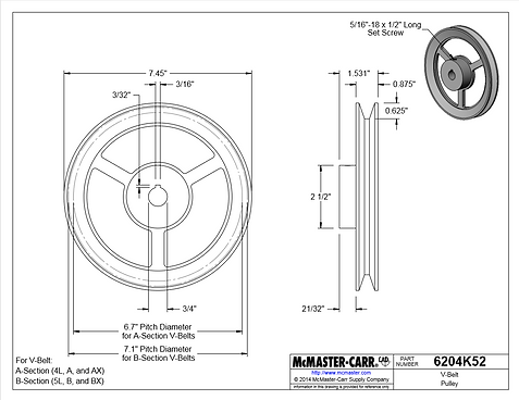
The idler roller is positioned right above the two 7.45 inch pulleys to add pressure and enough slip on the V-belt

These are the two v-belts being used on the pulleys to drive the system


bottom of page
